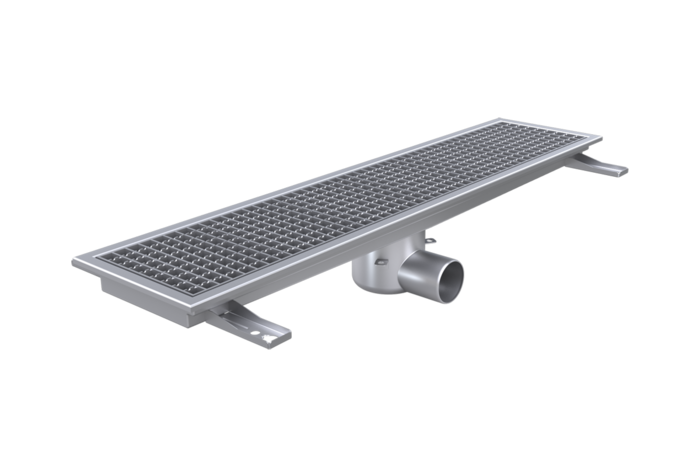
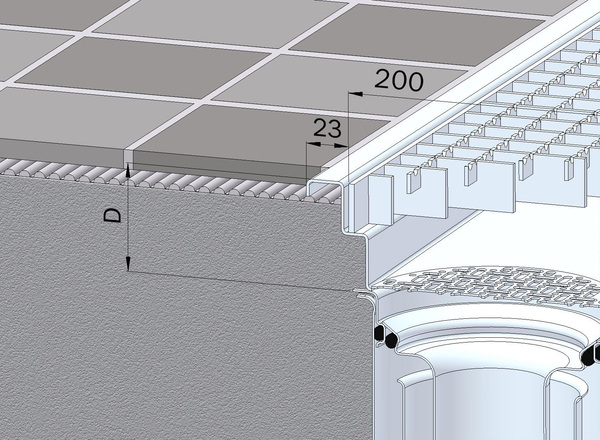
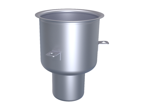
Floor drain channel, width 200 mm FURO 116
Variants
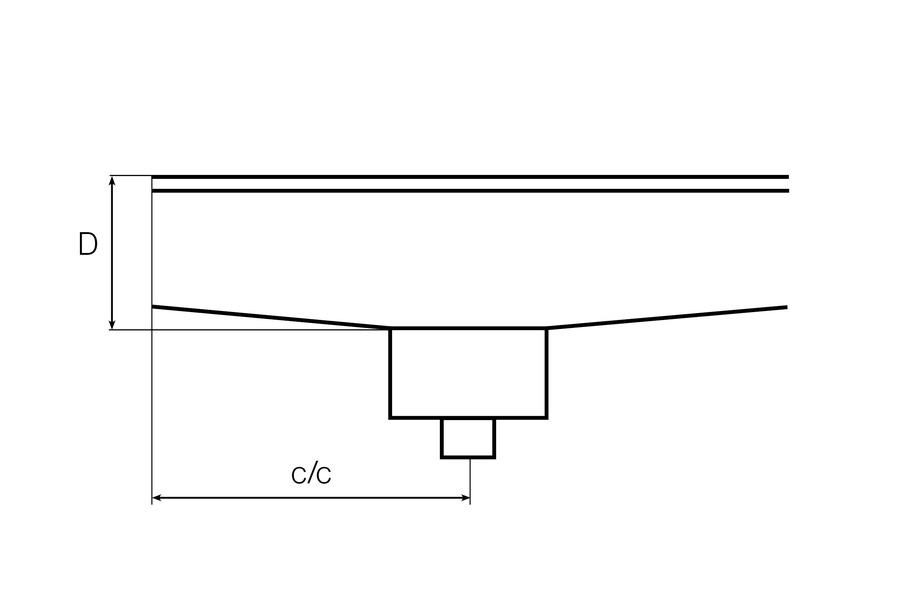
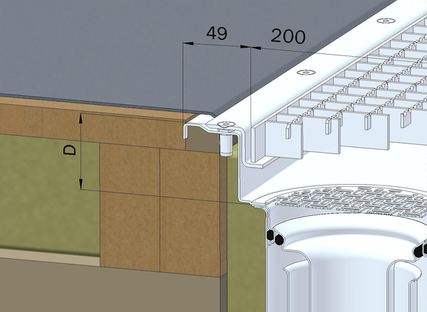
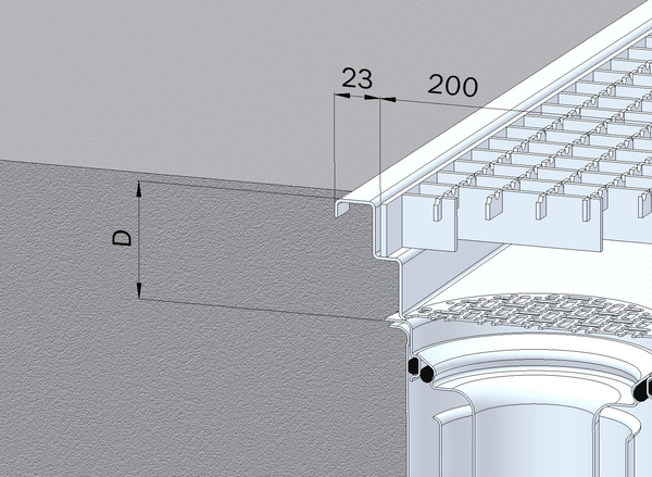
*For floor types Clinker K4 and K5, the depth dimensions differ from the above. For more information, see the section: "Water flow, total height, upper part depth, and slope towards the outlet"
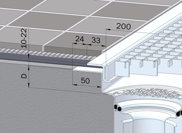
Clinker floor K3
Clinker floor K4
Clinker floor K5
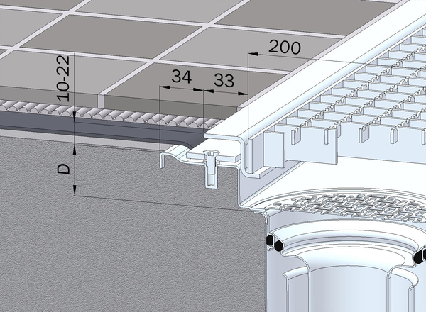
Resin flooring
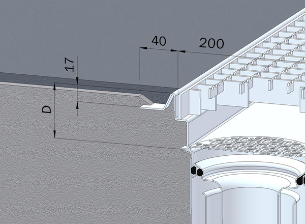
Vinyl flooring
Vinyl flooring on wooden beams
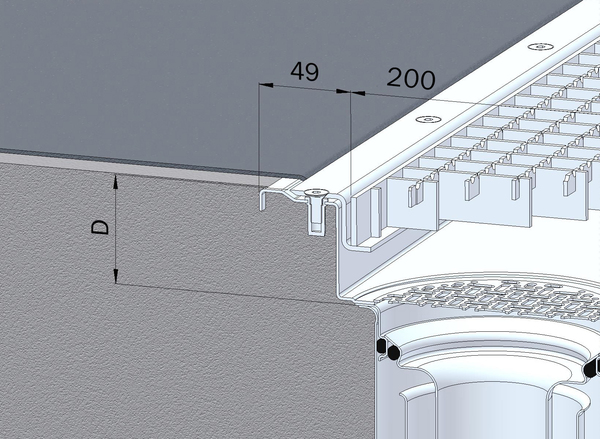
Concrete floor
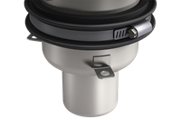
Trap
Trap included as standard.
Can be retrofitted.
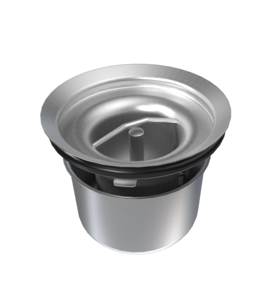
Trap with odor seal
Trap with mechanical odor seal.

Closable trap
A trap that can be shut off with a key. When choosing accessories, an extension part is required.
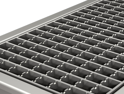
Slip-resistant grid, L15
Slip-resistant grid with load class L15.
- Maximum load: 1500 kg
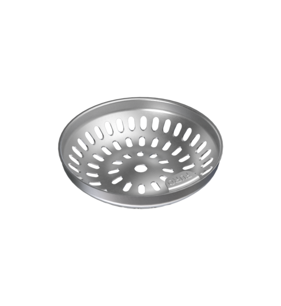
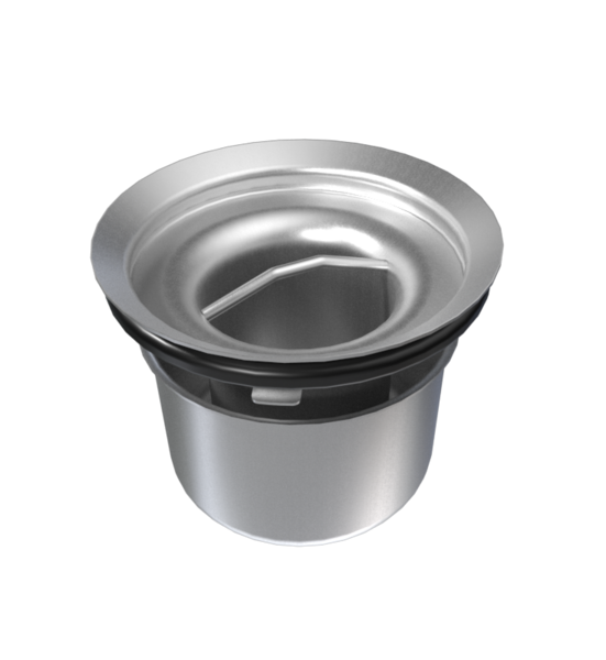
Strainer basket
Smaller filter basket.
- Volume: 2.5 dl
- Capacity: 1.2 l/s
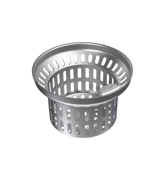
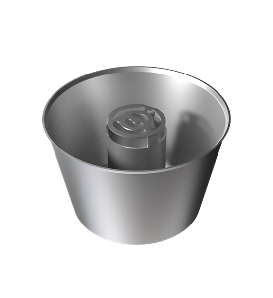
Strainer basket, 5 dl
Filter bucket suitable for drain without a trap and in a drain with additional extension part.
- Volume: 5 dl
- Capacity: 1.5 l/s
Sand trap 3 dl
Sand trap suitable for siphon configuration and in a drain with additional extension part.
- Volume: 3 dl
- Capacity: 0.6 l/s
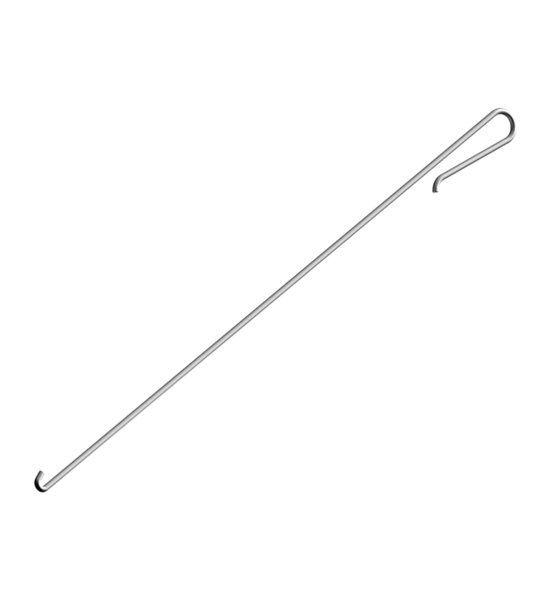
Lifting tool
Practical and ergonomic lifting hook for safe handling of grates and perforated plates. Provides a stable grip and reduces the risk of injury when lifting. Ideal for maintenance and installation.

Key for water trap
Key for locking Vater trap 126VA2.
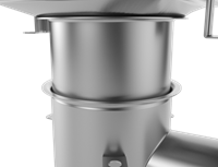
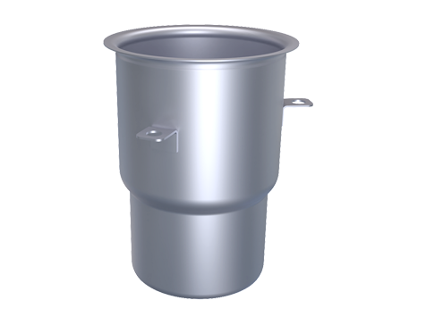
Extension part
Provides space for extra-large accessories.
Increases the total height by 60 mm.
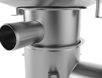
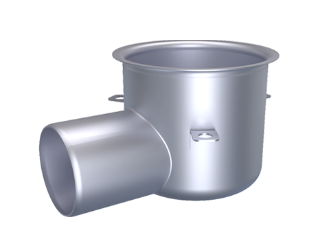
Inlet part
Inlet part with connection Ø 50 mm.
Increases the total height by 60 mm.
Radon sealing
Factory-installed radon and waterproofing.

Earth braid
Earth braid for potential equalization. Compatible with any attachment point on floor drains and channels.
For more information:
Installation instructions for earth braid
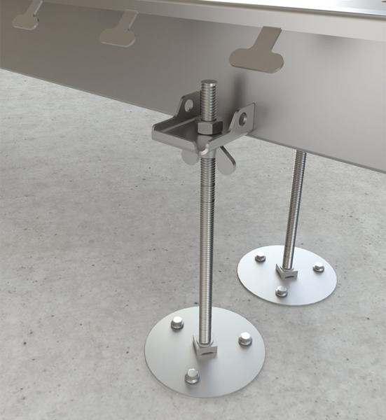
Mounting, threaded rod
Easy adjustment from above.
- Height 300 mm.
- Foot diameter = 100 mm.
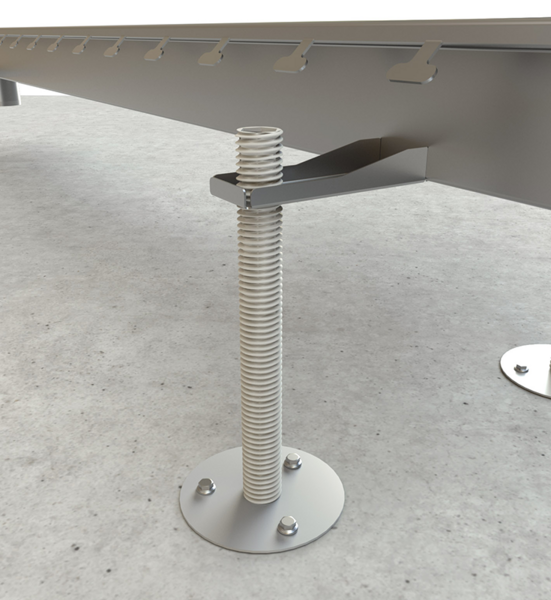
Plastic mounting rod
Mounting rod that allows for easy adjustment from above.
- Height: 300 mm
- Foot diameter: 100 mm.
Use together with Installation accessories "Bits for plastic mounting rod".
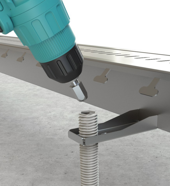
Bits for plastic mounting rod
For easy height adjustment of plastic mounting rod.
Sealant Aqua Tät
Sealant Aqua Tät for plastic flooring. Used under the flooring when installing the clamping frame.


Do you have any questions?
Do you have questions and concerns about production or do you need help with planning?
Common questions Contact usBIM
Do you need BIM or CAD files for your project? Download the files you need by clicking the buttons below.
Magicad Cloud MagiCAD Selection tool